Construction of the Underground Protected Building at CARP, Ontario 1959-62
The Use of the Critical Path Method of Project Scheduling and Control to Construct the E.A.S,E*. Facility
-A Major Technical Achievement-
Construction of the nuclear protected facility at Carp in 1959 -1962 involved overcoming a number of significant engineering problems. For instance at that time the impact of nuclear explosions in terms of air blast and ground shock wave prorogation as well as the effects of thermal, nuclear radiation and electomagnetic pulses were only just being understood and quantified to the point where they could be used in design calculations. In fact the engineers at Foundation Company of Canada in Montreal were designing and during the actual construction, building the facility and its ancillary structures somewhat ‘on-the-fly’.
Many other innovations were involved in getting the facility ready for human beings to live and operate in, ranging from the installation of the Iconorama in the Federal Warning Centre to the use of ‘crush blocks’ to prevent buckling of the wall partitions, to the special psychological aspects of the use of paint colours and patterns on the interior wall surfaces. However the main topic of this document is to discuss one of the most important technical achievements of the bunker’s construction, the use of the Critical Path Method of Project Management.
Background
The unknowns involved, the secrecy and urgency of the project along with funding and materials availability restrictions resulted in the project managers choosing to use the then relatively new project management tool, the Critical Path Method. It was sometimes referred to as Arrow Diagramming (because that’s what the project control sheet looked like – a bunch of interconnected arrows!). Googling the Critical Path Method (CPM) brings up many sources of information on this tool, including an excellent article in Wikipedia that provides good background on its origins https://en.wikipedia.org/wiki/Critical_path_method .
The video “The Nuclear Roof “shows a crude (looks like hand-drawn) version of a CPM diagram being used at a project management meeting where Lt Col Churchill, the military Project Manager is present. Col Churchill, a officer in the Royal Canadian Engineers would have been quite familiar with the technique as it was by then being taught to young military engineers (including myself).
I believe CPM was used by the U.S. Navy in the mid 1950s as a methodology for organising the building of nuclear submarines. Soon thereafter it was widely adopted by Canadian engineers (including Military Engineers) as an effective tool for many types of project management. My father was a plant design engineer and was using it in the late 50s and early 60s. I’ve used the method many times in my career including to build a bridge and a small bunker in CFB Gagetown. It is a very effective means of sequencing tasks, controlling resource allocation and dealing with unexpected changes.
How CPM Works
The two attached figures illustrate the use of CPM to plan the construction of a ‘bunker’ related component. The example is intended to be illustrative only and does not accurately depict an actual diagram used in the project.
The steps for producing a CPM arrow diagram include producing a list (or more directly, a logic diagram) of all of the tasks that have to be done to finish a project, complete with time durations of each of the tasks involved and their dependency relationships (figure 1). CPM facilitates calculation of the longest path (called the ‘critical path’) of planned tasks to the end of the project (the project duration).
Next a time-scale diagram (figure 2) is produced which further clarifies the ‘float’ (and non-float/ critical path) aspects of the various component tasks. It shows the earliest and latest start times that each task can start and finish at without increasing the project duration. The use of dummy arrows to account for non-activity dependencies is also necessary for logic purposes.
CPM diagrams also graphically depict where ‘fast tracking’, ‘crashing’, ‘resource levelling’ and other techniques can be applied to influence the duration and costs of a project. CPM can also be used to monitor and control the progress of a project and to make changes (with a full knowledge of the consequences) when required. The effects of such changes on the remainder of the project will quickly become apparent to the project management once an update review of the project diagram is undertaken.
Searching “Critical Path Method” and/or “Arrow Diagramming” in Google Images shows many examples of the use of the method. Some of these are much simpler that the two attached figures. We do have some of the original teaching books used by the engineer trainers (donated by Lcol Ken Holmes about 15 years ago).
Conclusion
The CPM diagram for the EASE project involved thousands of tasks and activities and was a prominent tool used in the Project Authority’s control office. As far as is known the construction of EASE facilities themselves were accomplished on time and on budget. However it seems that the fit-up of the army’s Strategic Radio (STRAD) System was plagued by delays, technical problems and cost overruns and was a bit late in being installed. This latter needs further research. The original STRAD control console is now located in the Signals Museum at CFB Kingston. In any case the Central Emergency Government Headquarters was sufficiently ready to support the Continuity of Government Program during the Cuban Missile Crisis in October 1962. Fortunately it never had to be used as such.
Dave Peters – Rev# 1 Nov 2017
* The construction of the “bunker” was done under the guise of being an Experimental Army Signals Establishment (E.A.S.E,) site to attempt to hide its significance from the enemy (The Soviet Union). This was not a very successful approach as exemplified by the unwanted press coverage that ensued. However the details of its construction and purpose were sufficiently muddied by subsequent press coverage so that other than the location (and there were many other related facilities to confuse the issue) it probably didn’t matter.
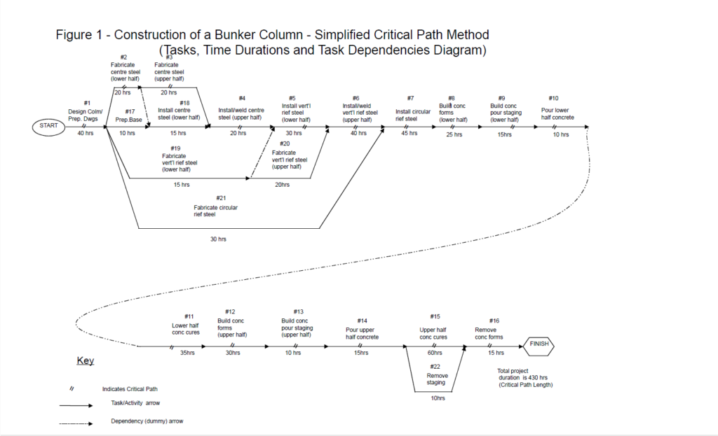
Figure 1 – Construction of a Bunker Column – Simplified Critical Path Method (Tasks, Time Durations and Task Dependencies Diagram)
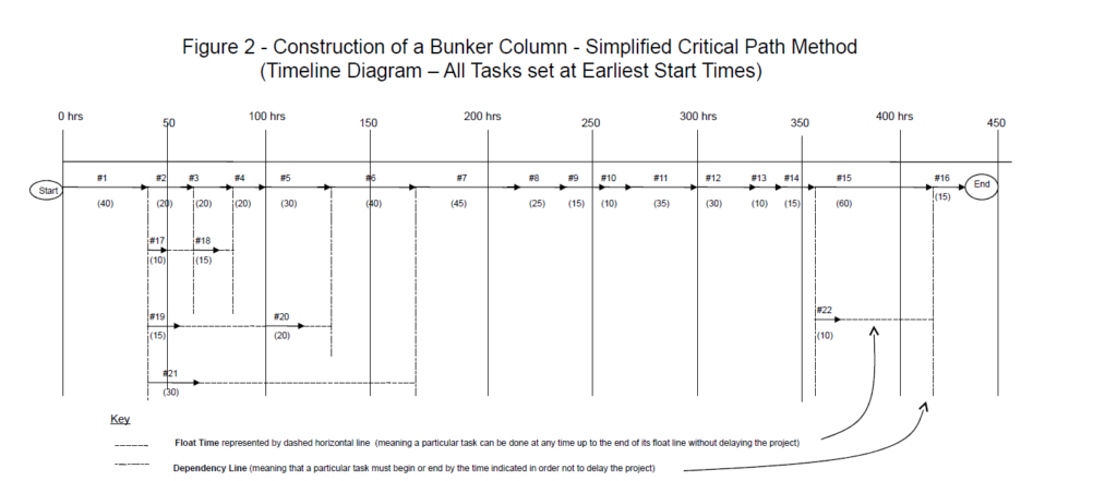
Figure 2 – Construction of a Bunker Column – Simplified Critical Path Method (Timeline Diagram – All Tasks set at Earliest Start Times)
Notes
The top line is the critical path and is the sequence of tasks which add up to the longest overall duration (shortest time possible to complete the project without fast tracking and/or crashing). “Fast Tracking” is performing more activities in parallel with the critical path.
“Crashing” the critical path is shortening the durations of one or more tasks on that path.
Both fast tracking and crashing usually require the addition of labour, materials and/or equipment, (all of which usually results in greater costs).
“Resource leveling” is a technique can be applied to a critical path diagram by examining the resources required for each task and reducing peak use of such resources (e.g.person-hours) either by using the available float times or accepting some delays to the project as an overall economy measure.
 Captain (N) (Ret’d) M. Braham, CD – Mike Braham is a graduate of the Royal Military College (1965) and a former naval officer and senior official with DND. He has an abiding interest in military history.


